Tape Saturation
Self-Oscillator
Pitch Shifted Delays
Spring Reverb
Looper
Phrase Sampler
Infinite Echo
Reverse
Clock Multiplier/Divider
Tape Stop/Start
Audio Scrubber
Stereo Operation
Tape Saturation
Warm Up Your Rack.
 Not only does Magneto deliver the warm, luscious delay signals that tape delays are known for, it is also capable of a high degree of saturation.
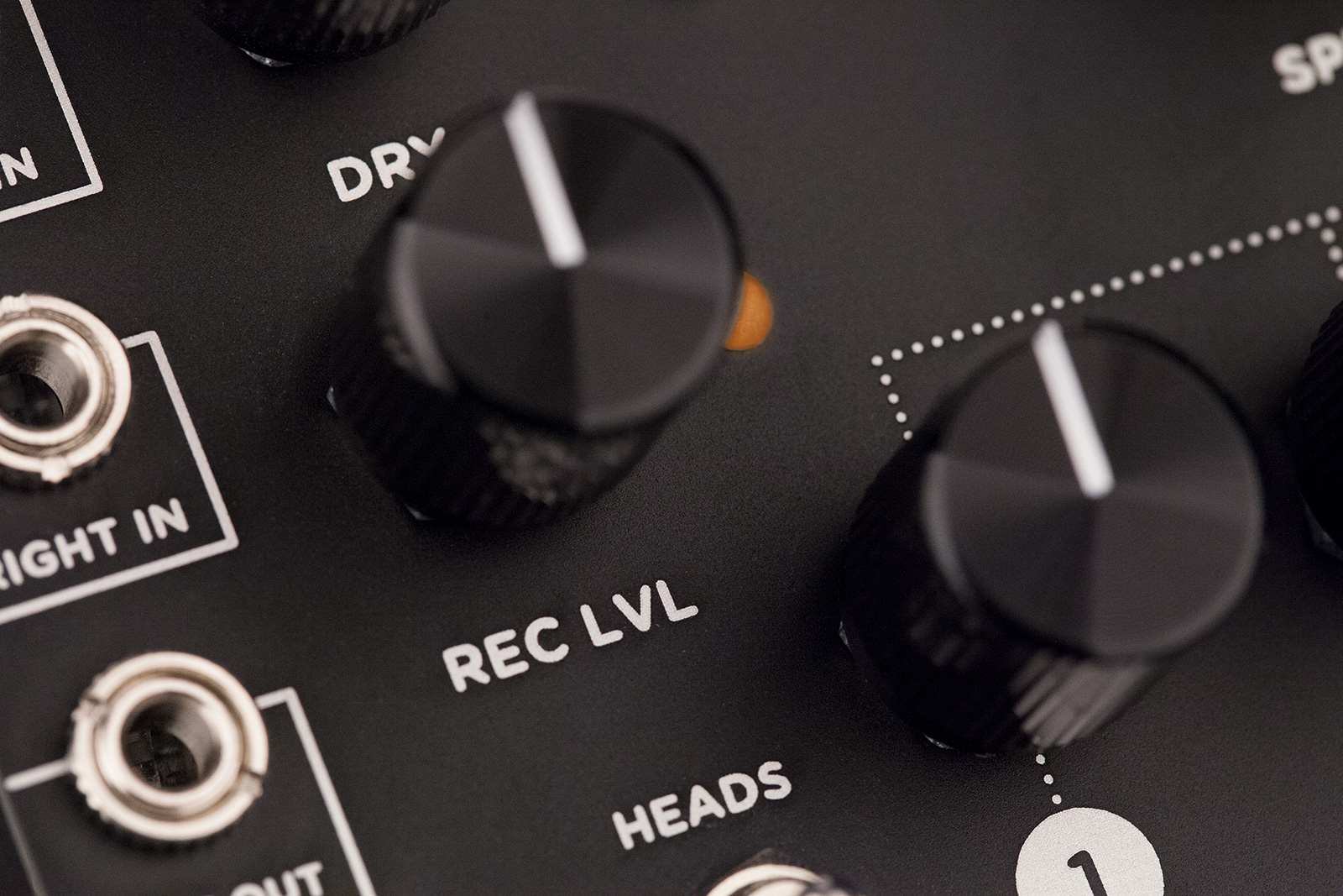
Turn up the Record Level knob to send a hot signal to the record head for any amount of tape saturation you desire.
Turn up the Tape Age control for warmer repeats. Add some truly beautiful Spring Reverb.
Magneto adds organic heart and soul to the sound of your modular.
Self-Oscillator
Otherworldly Oscillator.
 Tap in a fast delay time, crank up the REPEATS knob, and Magneto launches into beautifully singing self-oscillation.
Magneto will find evolving tonalities determined by the SPEED/PITCH setting (knob or 1V/octave CV), and the LOW CUT and TAPE AGE knobs.
Press the INFINITE transport button to capture a particular tonality.
Switch to Pitch Quantize mode and as you turn the SPEED knob, Magneto will play within any of 15 selectable scales.
Pitch Shifted Delays
Pitch Shifted Delays.
 In SHIFT mode, Magneto creates rhythmically pitched delays by changing the playback speed of each of the playback heads.
Head 1 plays back up one octave and a fifth at 3x speed, Head 2 plays up one octave at 2x speed, Head 3 plays down one octave at half speed (creating deep bass sounds), and Head 4 plays quarter note repeats with no pitch shift.
Use SHIFT mode to make things bigger and deeper, and to add melodic and rhythmic content.
In SHIFT mode, Magneto is also easily configured as a powerful zero-latency sub oscillator: Just run your gate signal to the Restart CV input and blend in only Head 3 with the DRY signal.
Spring Reverb
Spring Reverb.
 Some of the classic tape echo machines included small integrated spring reverb tanks tuned to limited bandwidth.
For Magneto, we captured this vintage vibe while creating a flexible, beautiful spring reverb that stands on its own, in addition to enhancing delayed signals.
The reverb circuit’s gain structure is designed so that when pushed hard, it will trash up nicely to hold its own with the funkiest lo-fi units, but when the input level is backed off, the reverb has a gorgeous, gentle character that enhances even subtle passages in a sophisticated and spacious way.
Looper
Sound on Sound.
 Just like one of our favorite moving head tape echo machines, Magneto gives you a Sound on Sound mode (LOOP Mode).
When you enter LOOP Mode, the machine is already recording, just like a traditional tape echo machine.
Tape head 4 is the looper playback head while tape heads 1-3 provide delay repeats for the incoming signal.
To set the length of your tape, press Tap once to set your splice “in” point, and press Tap again to set your splice “out” point.
All of the tone shaping knobs are active and affect your loop as it plays back and re-records.
Press Tap a third time to completely erase the tape. The REPEATS knob controls regeneration strength.
Set lower REPEATS level for loops that evolve over time.
The maximum loop length is 15 seconds at max SPEED, or two minutes at minimum SPEED.
Phrase Sampler
Phrase Sampler.
 Magneto includes a Phrase Sampler for recording a loop that is the length between two taps of the TAP button.
Just press the TAP button once to start sample recording, again to stop recording, and a third time to clear the sample memory.
You can trigger sample playback with the RESTART transport button or via the RESTART CV input.
The Speed knob or Speed CV determines the pitch and speed of the sample playback.
Infinite Echo
Infinity and Beyond.
 Want to just let Magneto continue to generate a soundscape while you play with some other modules?
In ECHO mode or LOOP mode, just press the INFINITE transport button at any time to disable the Record head and allow Magneto to continuously play the most recent delay cycle or loop length audio.
You can also engage INFINITE and use Magneto as an oscillator.
Reverse
Flip It And Reverse It.
 In ECHO mode, the entire tape contents (not just the current delay time) are played backwards when you press Reverse.
This allows for some very trippy effects when playing back sections that included SPEED manipulations or PAUSE events.
In LOOP or SAMPLE modes, the loop or sample length will play in reverse. You can continue recording new audio to layer with the reversed audio from the tape.
Clock Multiplier/Divider
Phase Aligned Clock Multiplier/Divider.
 Each of Magneto’s four tape heads has its own Clock CV output, phase aligned with incoming Clock or Tap CV signals.
In ECHO mode with EVEN head spacing, Head 1 outputs 4/1 (16th notes), Head 2 outputs 2/1 (8th notes), Head 3 outputs 3/4 (dotted 8th notes), while Head 4 is 1/1.
Different values are available in TRIPLET and SHIFT head spacings.
Tape Stop/Start
Mechanical Tape Stop/Start Effect.
 The PAUSE transport control is part of Magneto’s faithful recreation of a varispeed tape delay, with mechanical slowdown when pausing and mechanical speedup when coming out of pause.
The speed of this mechanical slowdown/startup effect is user-definable.
Audio Scrubber
Scrub Your Audio Clean.
 When the transport has come to rest after Pause is engaged, the Speed knob acts as an audio scrub tool.
The length of audio in the scrub buffer is determined by the position of the Speed knob when Pause is engaged, from 750ms at maximum speed, to 6 seconds at minimum speed.
Stereo Operation
Stereoize Your Modular.
 Double your dimension. Even if everything else in your rack is mono, plug into Magneto’s left input and enjoy instant stereo gratification.
Each of Magneto’s four playheads can have their outputs panned hard left or right (or center).
There are three pan modes: LRLR, LRRL, and (customizable) Center.
With all heads centered, a psycho-acoustic stereo image is produced.
Adding Wow and Flutter or the built-in Spring Reverb enhances the stereo field even further.
Magneto Videos


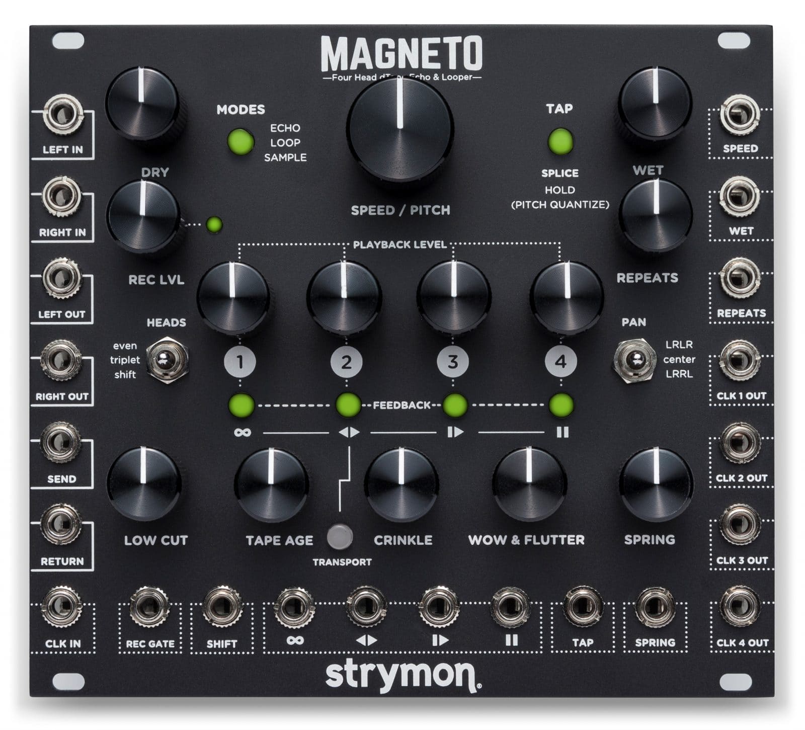
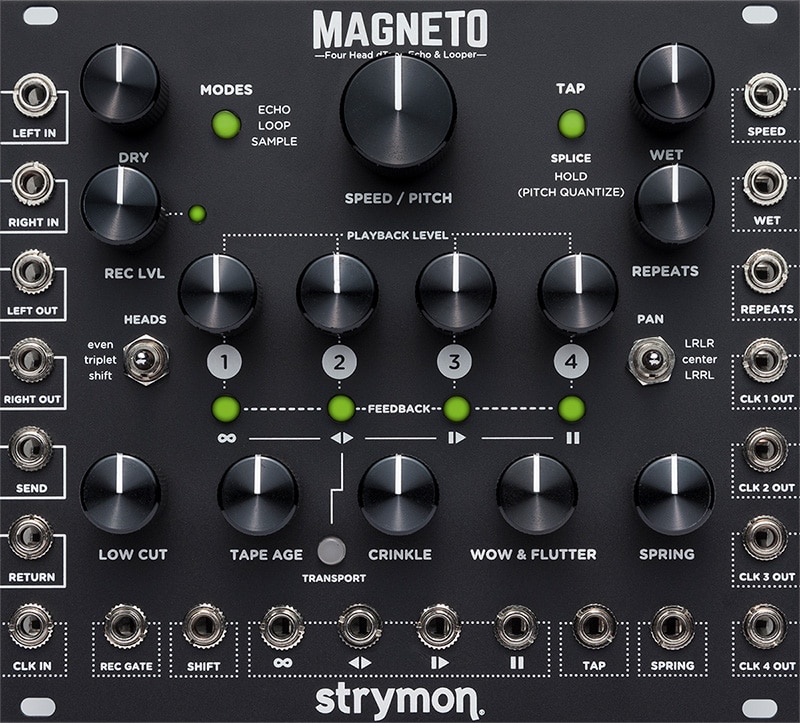
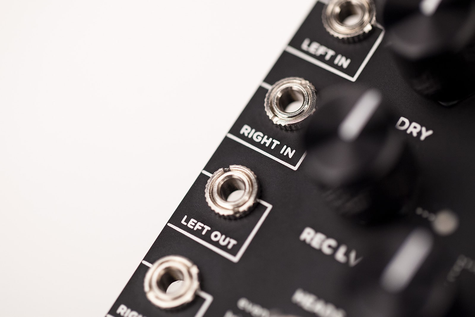
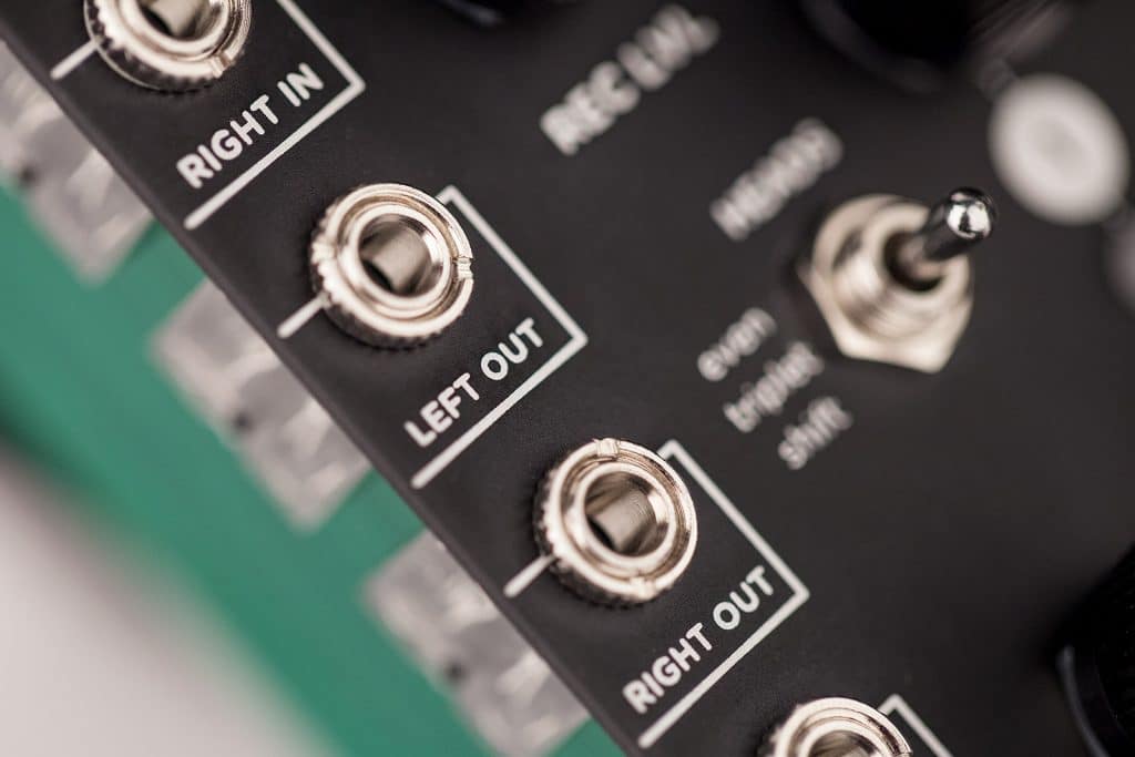
- LEFT IN: Left audio input. Use for mono input.
- DRY: Sets the level of DRY (input) signal sent to the output.
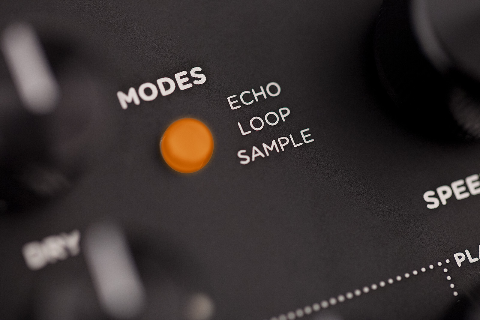
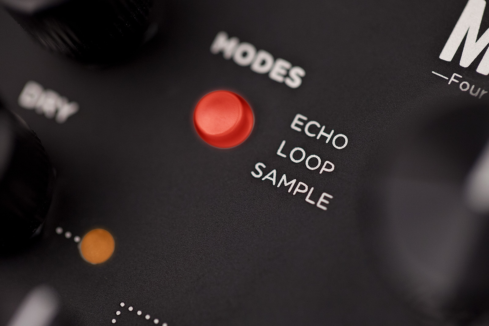
- ECHO: Four head tape delay with four playback heads and one record head.
- LOOP: Sound on Sound looper. Tape head 4 is looper playback, heads 1-3 provide delay repeats for incoming signal.
- SAMPLE: Phrase sampler records an audio phrase between two taps of the TAP button.
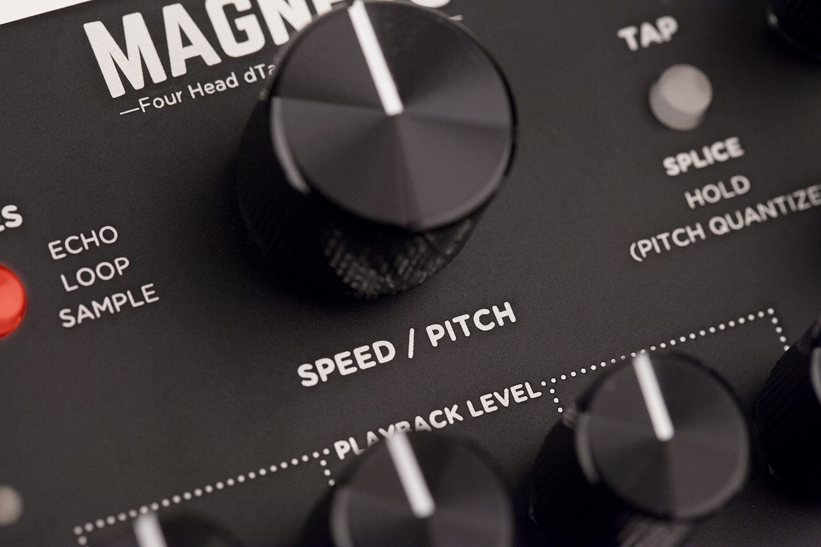
- SPEED / PITCH: Sets the speed of the tape machine. The tape speed also affects the fidelity of the delay repeats. Set high for cleaner delay repeats or low for a warmer tape sound. Any changes to the SPEED knob will result in a proportional change to the delay time of all the heads. Any audio in the delay line will shift in pitch proportional to the change in speed. When Magneto is Paused, acts as an audio scrub tool.
- TAP function depends on MODE selection.
- ECHO: Tap a delay time with two presses.
- LOOP: Tap to splice in, tap again to splice out and begin loop playback, tap a third time to clear loop.
- SAMPLE: Tap to start sample record, tap again to stop recording, tap a third time to clear the sample memory.
- WET: Sets the level of delay signal sent to the output.
- SPEED: Controls the tape speed. (-3V to +3V, calibrated for 1V/octave).
- RIGHT IN: Right audio input.
- REC LVL: Controls the level of the incoming unprocessed signal fed to the Delay Line Record head. When turned up, the delay signal becomes fatter and more saturated. Turn knob down to get cleaner delay signals.
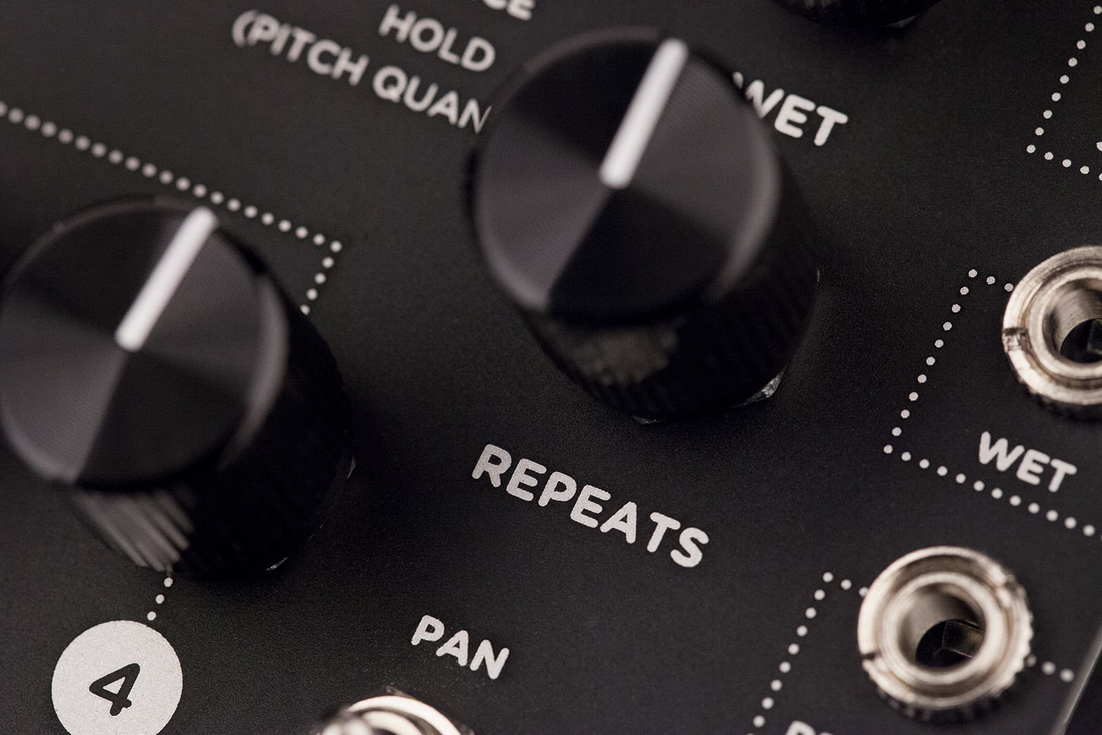
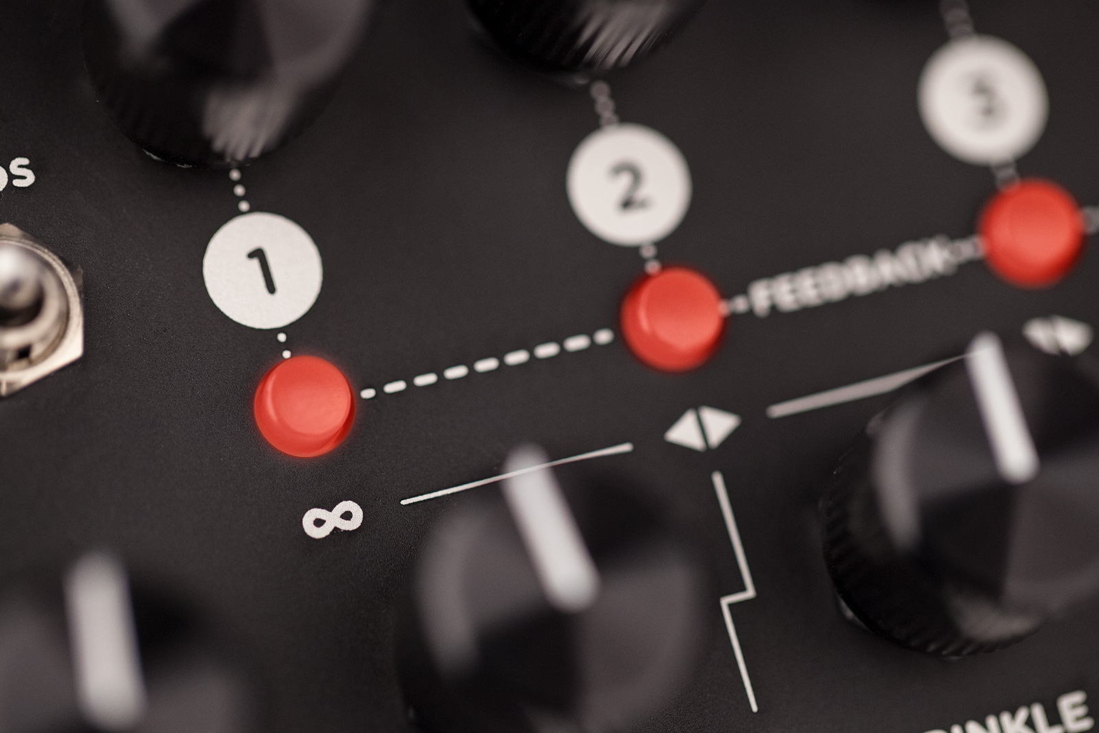
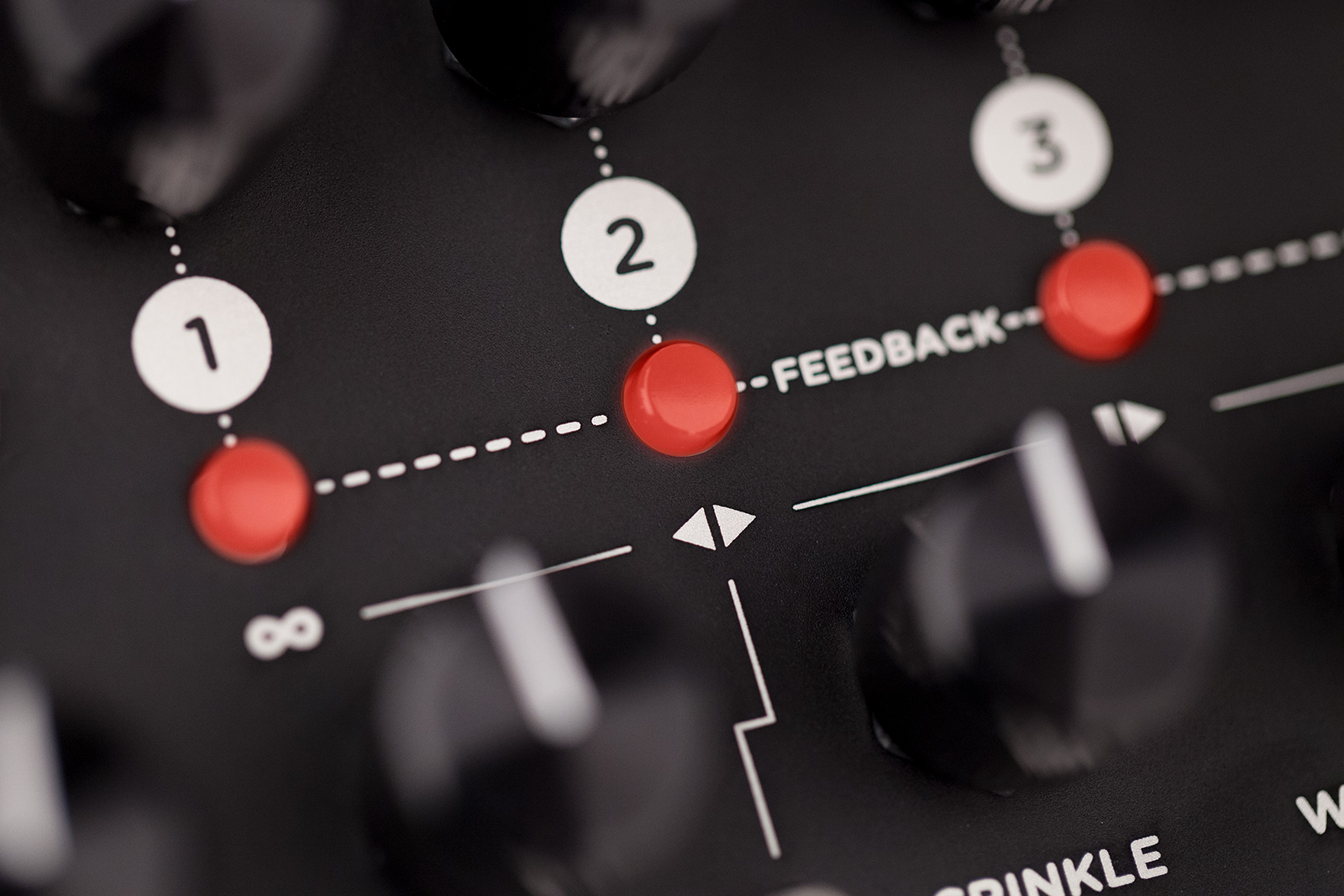
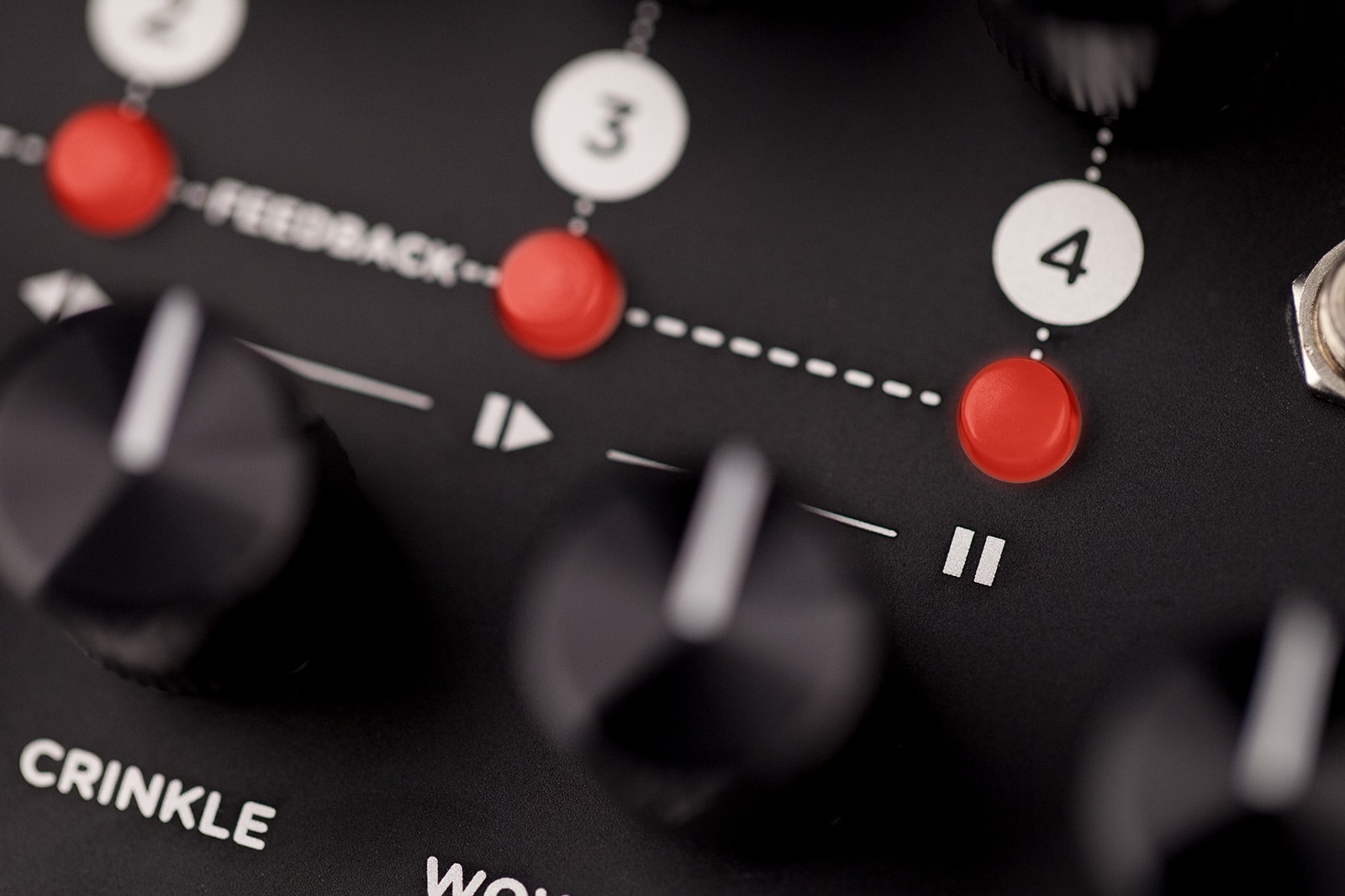
- REPEATS: Controls the feedback level of the delay repeats for the tape heads that have their FEEDBACK toggle set to ON.
- WET: Modifies the WET level. (-5V to +5V)
- LEFT OUT: Left audio output. If only one output is connected, Delay output sums to mono.
- PLAYBACK LEVEL 1: Sets the playback level for tape head 1.
- PLAYBACK LEVEL 2: Sets the playback level for tape head 2.
- PLAYBACK LEVEL 3: Sets the playback level for tape head 3.
- PLAYBACK LEVEL 4: Sets the playback level for tape head 4.
- REPEATS: Modifies the REPEATS level. (-5V to +5V)
- RIGHT OUT: Right audio output. If only one output is connected, Delay output sums to mono.
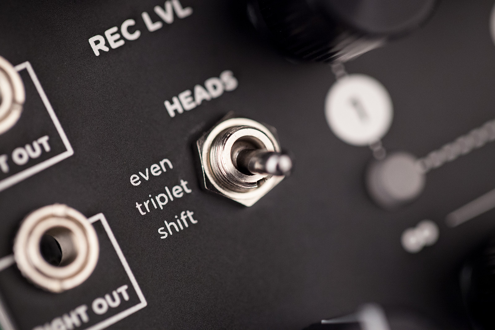
- HEADS: Selects between three different modes for the tape heads. Even spacing, triplet spacing, and rhythmic shifted pitches.
- FEEDBACK ON/OFF: Enables or disables feedback of tape head 1.
- If TRANSPORT is engaged:
- INFINITE: Disables the Record head and continuously plays the most recent delay cycle or loop length audio.
- FEEDBACK ON/OFF: Enables or disables feedback of tape head 2.
- If TRANSPORT is engaged:
- FORWARD/REVERSE: Reverses the playback direction of the tape from the moment the function is engaged.
- FEEDBACK ON/OFF: Enables or disables feedback of tape head 3.
- If TRANSPORT is engaged:
- RESTART: Restarts the playback of the loop or sample from the starting point in LOOP or SAMPLE mode. Aligns shifted head audio in ECHO operation.
- FEEDBACK ON/OFF: Enables or disables feedback of tape head 4.
- If TRANSPORT is engaged:
- PAUSE: Stops/Starts the playback of the tape with mechanical slowdown/startup effect.
- PAN: Selects between three different stereo panning modes for the tape heads. Custom panning is available.
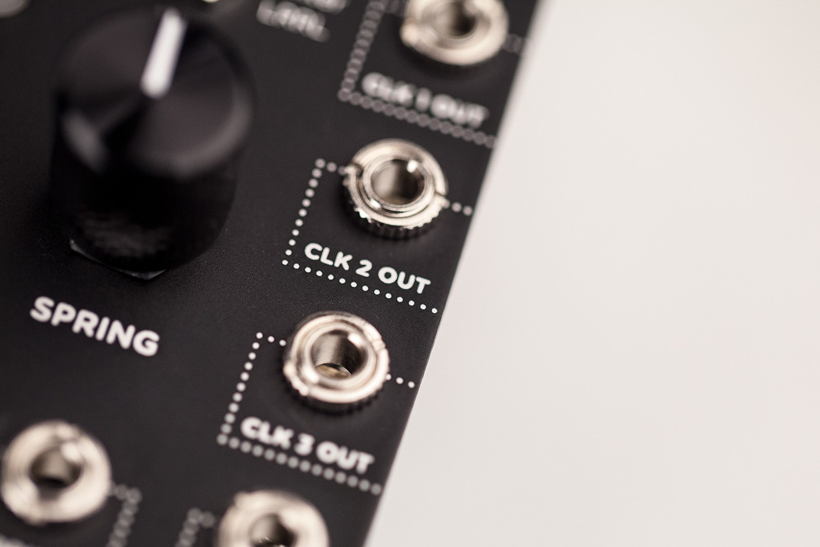
- CLK 1 OUT: Send clock output of Playback head 1. Dependent on MODES setting and HEADS switch.
- SEND: Delay repeats generated by Magneto are sent out to be processed by other devices.
- LOW CUT: Controls the low frequency shaping of the echo repeats. Set to minimum for extended low frequency bandwidth. Set to maximum for extremely high-passed, magnetic drum style repeats.
- TAPE AGE: Controls the bandwidth of the tape. Set to minimum for a fresh, full bandwidth tape. Turn clockwise for warmer repeats.
- TRANSPORT: Press to toggle functionality of the four buttons above it.
- CRINKLE: Controls the amount and severity of tape irregularities including friction, creases, splices, and contaminants. Set to minimum for a fresh, clean tape. Set to maximum for a tape that has been mangled and chewed.
- WOW & FLUTTER: Controls the amount of mechanically related tape speed fluctuations. Turn the knob fully counterclockwise for a perfectly tuned tape machine or fully clockwise for a tape machine in need of service.
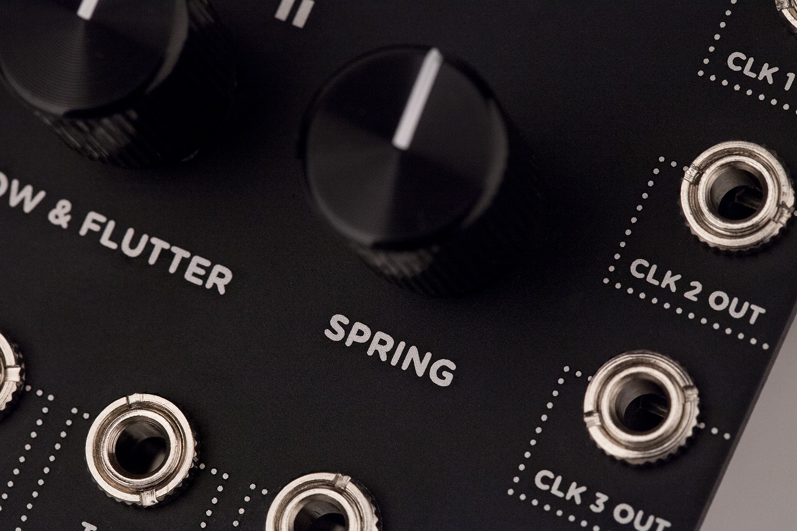
- SPRING: Controls the output mix of the integrated spring reverb tank. The DRY and WET knobs control the signals feeding into the spring reverb effect.
- CLK 2 OUT: Send clock output of Playback head 2. Dependent on MODES setting and HEADS switch.
- RETURN: Processed delay repeats are returned back to be mixed in with the dry input signal.
- CLK 3 OUT: Send clock output of Playback head 3. Dependent on MODES setting and HEADS switch.
- CLK IN: Sets the delay time in quarter notes. (0 to 5V rising edge trigger) Clock period range – 50ms to 15s.
- CLK 4 OUT: Send clock output of Playback head 4. Dependent on MODES setting and HEADS switch.
- REC GATE: Toggles the record head ON and OFF, REC LVL LED lit BLUE when input signal to the delay line is muted. (0 to 5V rising edge trigger)
- SHIFT: Toggles the SHIFT effect for the Playback heads on and off. (0 to 5V rising edge trigger)
- INFINITE: Toggles INFINITE transport control on and off. (0 to 5V rising edge trigger)
- FORWARD/REVERSE: Toggles the FORWARD/REVERSE transport function. (0 to 5V rising edge trigger)
- RESTART: Engages the RESTART transport function. (0 to 5V rising edge trigger)
- PAUSE: Toggles the PAUSE transport function. (0 to 5V rising edge trigger)
- TAP: Sets delay time in ECHO mode. Sets splice in/out/clear in LOOP mode. Sets sample record start/stop/clear in SAMPLE mode. (0 to 5V rising edge trigger)
- SPRING: Modifies the SPRING reverb level. (-5V to +5V)
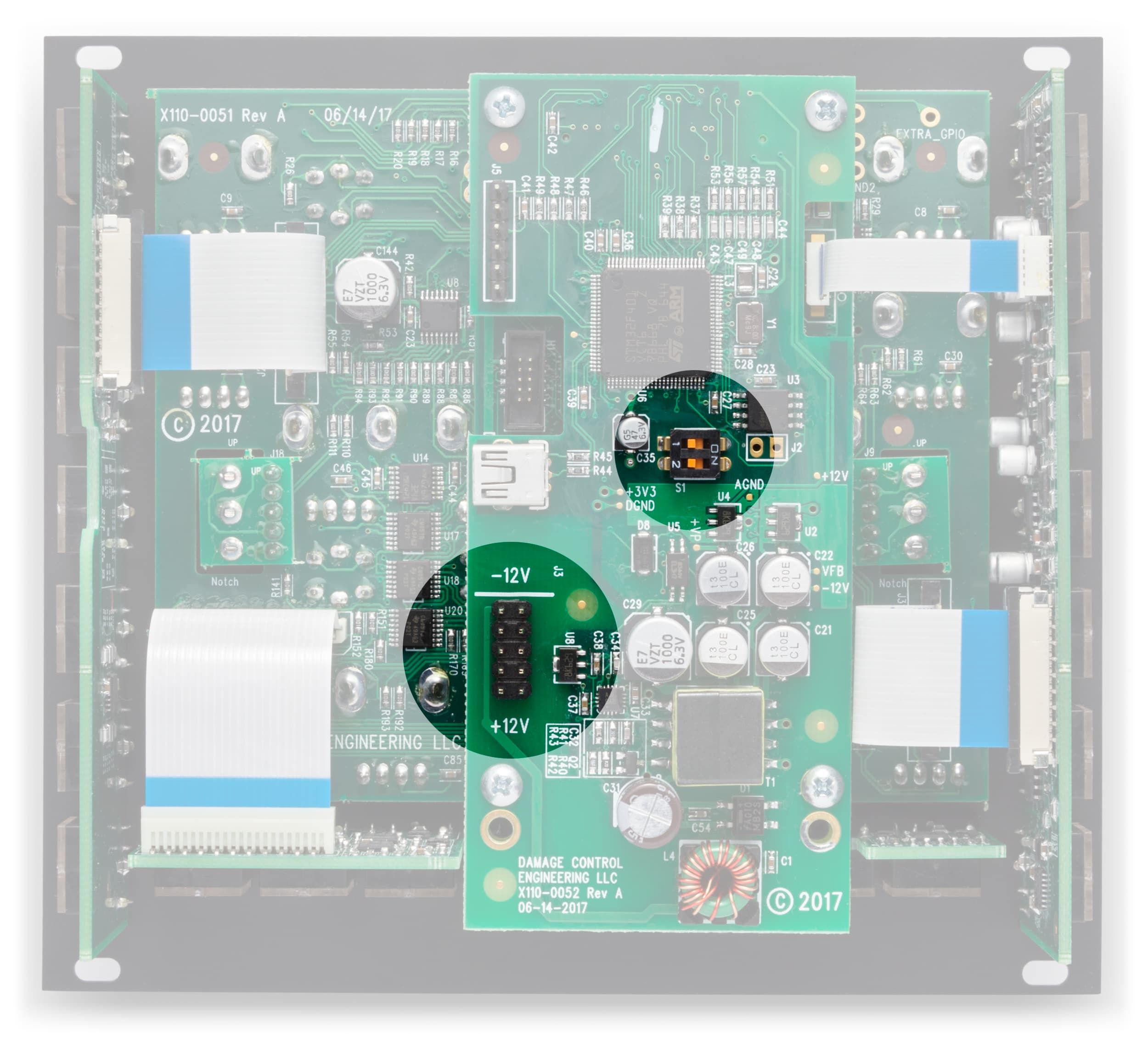
- POWER: Power your Magneto here.
- +12V rail: 210mA
- -12V rail: 210mA
- +5V rail: 0mA
- DIP SWITCH 1 – FEEDBACK CV MODE:
- ON: Allows for advanced CV trigger control of the FEEDBACK ON/OFF buttons (see user manual for complete detail).
- OFF (DEFAULT): Standard CV control of transport whenever transport CV jacks are plugged in.
- DIP SWITCH 2 – DUAL SPLIT MODE:
- ON: Selects Dual Split mode where LEFT audio IN/OUT is a mono four head tape delay, and RIGHT audio IN/OUT is mono spring reverb.
- OFF (DEFAULT): Standard stereo IN/OUT with the delay signal feeding into the Spring reverb.

Reviews, Demos, and More
9 Videos

5:43

11:22
30:27

13:42

14:54

9:17

21:42

3:46
